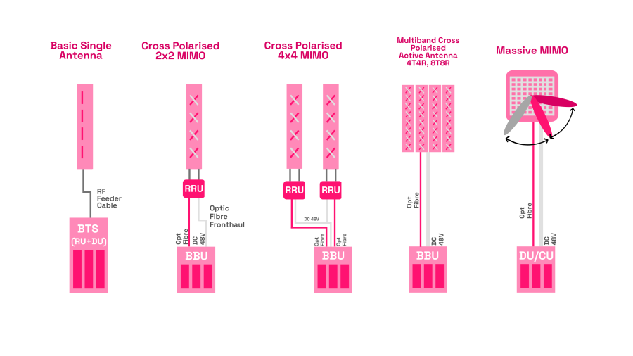
In 2G and early 3G days, the Radio Unit (RU) was typically either part of the Baseband Unit (BBU) or co-located with it, usually at ground level. The RF cable from the RU to the antennas typically attenuated the RF signal by 3 decibels (dB), resulting in the RF signal reducing by half from the RU to the antenna.
To address this, RUs were placed on the mast, close to antennas, and in such architectures became known as Remote Radio Units (RRU) or Remote Radio Heads (RRH). Optical signals are sent to the RRU from the BBU via a fibre optic cable, referred to as Fronthaul. In 5G, the BBU is split into the Distributed Unit (DU) and the Centralised Unit (CU).
The RRU typically contains an Analog-to-Digital Converter (ADC), Digital-to-Analog Converter (DAC), Filter and Power Amplifier. In 5G New Radio (NR) - unlike previous mobile generations - an RRU may also contain 5G layers one and two in the RRU, based on the 5G RAN functional split being used. 3GPP defines eight RAN functional splits for 5G NR with some of these having further sub-splits. The O-RAN Alliance uses split 7.2 in its architecture which puts the lower part of layer 1, Low-PHY, in the RRU.

The antennas are generally the most visible part of the mobile network. They transmit radio frequency (RF) signals that are received by smartphones and other devices, collectively referred to as User Equipment (UE). The same antennas transmit and receive the signal to and from many different UEs.
Antennas are often shown radiating the RF signal equally in all directions (omnidirectional antennas), but at most base stations antennas are in fact directional i.e. only radiate signals in a specific direction. Omnidirectional antennas are typically only used at small low-power cells.
The most common deployment topology uses three-sectored sites. Here, each antenna radiates and receives signals over an arc of 120 degrees, with three antennas delivering full 360 degree coverage.
2G and 3G base stations employed two antennas to provide receive diversity; initially by pairs of antennas providing spatial diversity but at later base stations the two antennas employed polarisation diversity and were accommodated in a single physical form factor for each sector. The same antenna arrangement also provided transmit diversity for later enhancements of 3G (HSPA). 4G by contrast developed the use of more than one antenna for each sector. Typically two antennas are deployed to support signal processing arrangements commonly referred to as 2x2 MIMO (Multiple Input Multiple Output). The term MIMO describes all scenarios with more than one transmit-and-receive antenna. A single antenna for transmit-and-receive is known as Single Input Single Output (SISO).
MIMO techniques exploit multipath propagation between the base station and the UE to send and receive more than one data signal simultaneously over the same radio channel. This both improves the reliability of the transmitted and received signal using diversity, and increases the data rates using spatial multiplexing. There may be a different number of antennas used for the uplink and downlink. Formerly referred to as m x n (pronounced 'm cross n') MIMO, these are now designated as mTnR, where m and n are the number of transmit and receive data signals respectively. So 4T4R provides four transmit and four receive streams, typically supported by a pair of dual-polarised base station antennas.
Massive MIMO (mMIMO) in 5G NR generally refers to 32 or more simultaneous data streams being transmitted or received on the single RF data channel. Most common deployments for mMIMO in 5G NR today are 32T32R and 64T64R.
Most operators have to support multiple generations of mobile technology, with each generation usually having multiple frequency bands. Modern base station antennas are therefore complex devices, typically housing as many as 16 independent antenna arrays. Each dual-polar pair of antenna arrays is connected to an RRU that provides high power transmit signals and processes the received signals. Each antenna array is ‘passive’, there are no amplifiers within the array itself. Its azimuth pattern – how the antenna radiates on the horizontal axis - is fixed by design with the ability to vary the elevation angle of the main beam of each dual-polar array in response to signals from the network controller. Typical base stations use antennas with azimuth 3-dB beamwidths of around 65 degrees and elevation beamwidths between five and 10 degrees, with the main lobe adjustable between zero and 12 degrees below the horizontal.
The quest for higher capacity at base stations has prompted the development of antennas in which each individual antenna element (for example a dipole) is connected to RF amplifiers excited by signals that, operating together, form one or more narrow directional beams in both uplink and downlink directions. The transmitters, receivers and antennas now form one unit, commonly referred to as an ‘active’, ‘beamforming’ or ‘smart’ antenna, connected to the BBU by a fibre and DC power supply. The possible capabilities of beamforming antennas have been extended in successive releases of 3GPP specifications and are likely to be further extended in the future.
The frequencies used determine the dimensions of antennas. The lower the frequency, the larger the antenna size. Antennas are smaller at higher frequencies, so multi-element active antennas are more commonly found at frequencies above 2 GHz. This becomes important as we move towards using higher frequencies in 5G, especially millimetre waves (mmWaves) where they can be integrated into UEs.
The size of antennas is important as it affects the wind loading on a supporting structure; in rooftop deployments the additional weight of large antennas may require reinforcement of the roof. It also impacts the visual profile of the base station in the environment and can influence public acceptance and opinion.
For antennas and radio units, the key issues for Open RAN are:
- Comparable performance to incumbent systems
- Supporting variable splits depending on deployment type
- Cost compared to incumbent systems
- Plug and play interoperability with a range of fronthaul and distributed unit products.
FRANC (Future RAN Competition) run by DSIT, has allocated up to £30 million of R&D funding to projects that support the goals of the government's 5G Supply Chain Diversification Strategy. The competition aims to help to incentivise industry to create new products and services to unlock the full potential of Open RAN. Several of these projects are exploring antennas and radio units:
- Future RAN Radio Test System
- ORanGaN
- Secure 5G platform using novel, efficient, wideband PA
The University of Surrey is an academic partner to the Flex-5G project. They focus on developing fundamental research through to practice in the interdisciplinary area of antennas and propagation, signal processing, mmWave and 'internet of things' technologies for mobile and satellite applications, and aim to bring digital closer to the RF and antennas.
UK Industry Participants
Through the FRANC projects, there are a number of UK based organisations actively undertaking R&D into Open RAN in this space: